Tel. +49 (0) 7151.20534-0
info@smz-spindelservice.de
Spindle knowledge
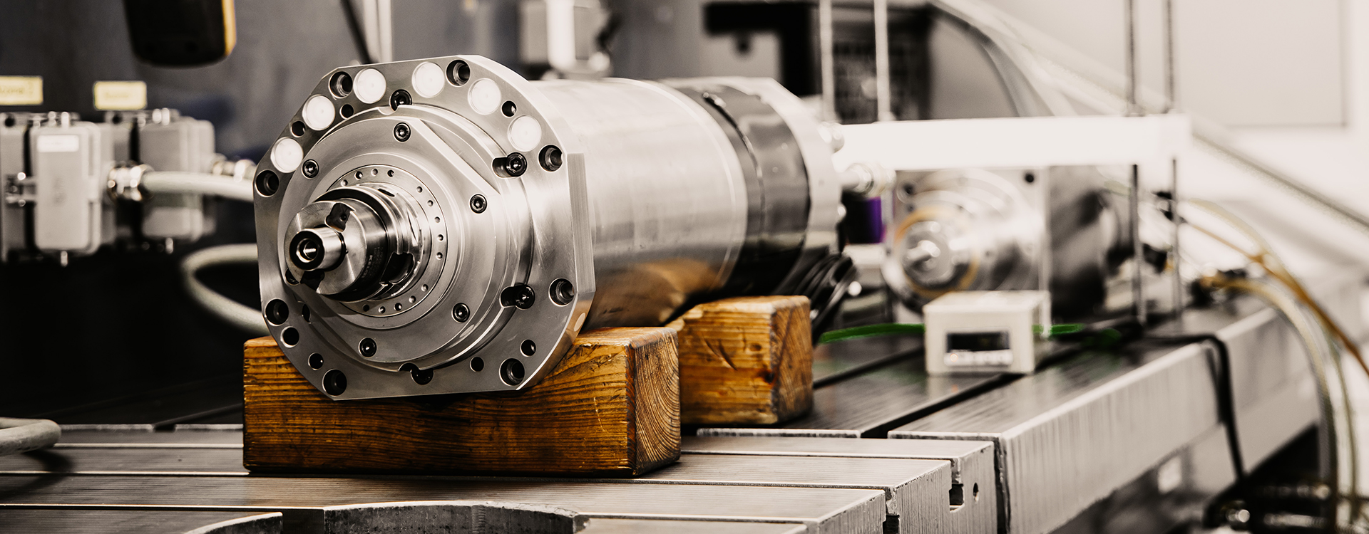
A motor spindle is a directly driven shaft mounted in precision bearings with integrated tool interface. The motor spindle is an important assembly in many modern machine tools.
Classic motor spindle
Motor spindles are generally mounted in anti-friction bearings and driven electrically. Thanks to the direct coupling of the drive with the shaft in its precision bearings, very precise machining of the workpiece is possible at high rotational speeds. When machining a workpiece using a tool by rotation, it makes no difference which of the two rotates. That is why with motor spindles, as with spindles in general, a distinction is made between tool-bearing and workpiece-bearing spindles. Tool-bearing motor spindles are typically used in drilling, grinding and milling machines, while workpiece-bearing motor spindles are more commonly found in lathes. Apart from the drive and the shaft bearing, the tool interface is one of the most important components of a modern motor spindle. The tool is changed automatically and fixed by a clamping or chucking system. That is why the motor spindle is nowadays the central assembly of a machine tool and mainly responsible for its performance and precision. Due to the complex structure and interaction of the individual components, motor spindles are not standard products and are developed and produced to meet individual requirements. The main fields of application for motor spindles are machining centres and CNC machine tools for turning, grinding and milling, high-speed cutting (HSC), high-performance cutting (HPC), mould and die making, automotive production and aerospace.
History
The spindle (also called main spindle or work spindle) is a historically evolved term that, in the context of machine tools, refers to a shaft with an integrated interface for holding a workpiece or a tool. This shaft performs a rotary motion so that the workpiece is machined with the tool, either by rotating the tool (e.g. milling machine) or rotating the workpiece (e.g. lathe), depending on the application. Increasing demands on machine tools, particularly in the area of high-speed cutting, made it necessary in the 1980s to drive the tool-bearing spindles directly to enable more precise machining at higher rotational speeds. The rapid developments in tool geometries and tool materials that began at this time allowed higher cutting speeds in machining operations, resulting in higher rotational speeds. These high speeds could now hardly be guaranteed any longer, or only with considerably greater effort, using the conventional drive technologies, which usually coupled the drive and the work spindle by means of a gearbox and other transmission elements. At the same time, the first variable-speed electric motors were developed which, together with the advances in ball bearings and frequency converters, led to the development of the motor spindle. A gearbox was now no longer required to achieve the necessary speeds, and instead the spindle was coupled directly to the drive. In the 1990s, many machine tool manufacturers began outsourcing whole departments due to the crisis in the industry. As an independent assembly, the motor spindle was very well suited to outsourcing, which led suppliers to specialise in the development of motor spindles. The compact design, simple and safe maintenance, lower noise emissions and the readiness of specialist companies to supply are further advantages of the motor spindle, as a result of which its range of applications has now greatly expanded and is no longer limited to the field of high-speed machining.
Design
The basic design of motor spindles is often the same, regardless of the manufacturer. The main differences depend on the spindle application, which can be divided into the functional classes of milling spindles, workpiece spindles and internal grinding spindles. Workpiece-bearing spindles, in particular, often have different requirements.
Housing and cooling
The overall shape of the spindle is determined by the installation dimensions in the machine tool. A key feature of motor spindles is their compact design, which has a positive effect on the space required for installation in the machine. Consequently, sufficient cooling of the motor must be ensured, for which both air and water are used. The most frequent solution is a water cooling system for the stator integrated into the housing.
Shaft
The central element of the motor spindle is the work spindle, a shaft with an integrated tool interface. The shaft must be stiff enough not to bend under the action of radial forces. The aim is to achieve the highest possible stiffness, a factor determined in principle by the diameter of the shaft and the material. A larger diameter, on the other hand, leads to a higher mass moment of inertia, which in turn increases the energy required for acceleration. In addition, the dynamic behaviour of the shaft plays an important role. The rotating shaft, together with the drive and bearings, represents a system that can oscillate; these oscillations can cause serious damage when they reach their resonance frequency. In addition, more and more machine tools require an internal coolant supply. Here the coolant is fed via a rotary union into an axial bore in the shaft up to the tool. The actual tool must have small bores through which the coolant can escape and thus cool the tool. Additional lubrication for the machining operation can also be provided by a cooling lubricant. In addition, a supply of cleaning air is increasingly required, which can be used to blow away any machining residues, e.g. chips. This can be done either by means of a separate bore in the shaft or by again using the coolant bore; in this case the remaining coolant first has to be blown out.
Tool and workpiece interface
A tool-bearing work spindle on a machine tool is really only expedient if the tool can also be changed. Modern machine tools should work as automatically as possible, and thus also be able to change the tool automatically. A “tool interface” is therefore required that allows a very high repeat accuracy, i.e. the same tool that is clamped twice in succession should run with exactly the same precision. This precision during running has a direct effect on the machining precision. A lack of precision, on the other hand, results in an unbalance that can affect the whole process and at high rotational speeds have serious consequences. The steep (short) taper and the hollow shank have established themselves as the predominant tool holders. The hollow shank has some advantages, particularly at high rotational speeds, but steep taper tools are still widely used, which is why the steep taper is still found. Hollow shank tools will be found almost exclusively for high rotational speeds, such as on machine tools in the automotive industry or for HSC applications. In addition to the tool holder, the tool interface of a high-performance motor spindle also has an automatic tool chuck that has the task of fixing the tool on the spindle. Here there is a choice between hydromechanical or mechanical systems, i.e. spring-loaded systems. The sturdy cup-spring chuck is still by far the most frequently used system here. The tool is released by means of a hydraulic or pneumatic release unit that presses against the spring force and thus releases the tool when the tool is at a standstill. New on the market are tool chucks with a gas spring, but these are currently still at the trial stage. By analogy with the tool-bearing spindles, workpiece-bearing spindles also have an interface, although this is generally referred to as a chuck. The workpiece is rarely changed automatically, however, since the workpieces to be machined usually differ in their overall form and the necessary mounting.
Drive
Open motor spindle for teaching purposes. Rotor and stator are clearly visible. Another essential component of the motor spindle is the drive in the form of an electric motor. Here the nature of the motor spindle as a direct drive comes to the fore, since there is no gearbox for transmission between the drive (motor) and the output shaft (spindle) as is the case with externally driven spindles. The motor design in terms of rotational speed and torque must therefore directly meet the desired requirements of the spindle. The maximum power of a motor is directly proportional to the stator volume; at the same time, the motor is an integrated component and must consequently conform to the spatial, usually very compact, dimensions of the headstock. A further problem here is the waste heat that increases with the continuous output of the motor and has to be dissipated by adequate cooling. For these reasons, it is very difficult to increase the motor power within the given spatial conditions so that it quickly reaches its limits. Conversely, optimum motor power must be demanded under the given spatial conditions, which is the essential task in the design of the motor. One approach here is to increase the quality of the current signal, for which the frequency converter is responsible. The frequency converter should be optimised so that the current has as ideal a sinusoidal signal as possible, thus reducing the power loss and increasing the continuous output of the motor. The type of motor ultimately used depends entirely on the application. Synchronous motors are mainly suitable for spindles that have to generate high torques at low speeds. Here, a significantly higher torque can be generated with the same motor volume and the same current. Another application for synchronous motors can be seen in highly dynamic, high-speed spindles that have to deliver low continuous outputs. Asynchronous motors have their advantages particularly in the area of "standard motor spindles", i.e. spindles for universal machining centres with speeds of up to 20,000 rpm where relatively high torques are needed in the lower range while still requiring sufficient power at high speeds.
Bearings
The bearings of the shaft also have a significant influence on the oscillation (vibration) behaviour of the system and must be adapted to the requirements accordingly. Until now, angular-contact ball bearings, also known as spindle bearings, have been used almost exclusively in spindle construction. Angular-contact ball bearings can absorb not only radial forces but also axial forces acting on one side caused by the infeed. The high rotational speeds of the shaft cause high centrifugal loadsin the ball bearings, which is why hybrid ball bearings (ceramic balls, steel races) are now frequently used. The use of ceramics (silicon nitride) for the balls allows the strength to be increased and the density decreased, thus reducing the centrifugal force. Angular contact ball bearings are always installed in pairs. Depending on the speed and mechanical load, the bearings are paired differently, in the simplest case in an O arrangement Because of the ease of handling, the majority of spindles are still greased for life. Mostly non-toxic synthetic greases are used, the base oils of which are continuously fed to the bearings over a very long period. In recent years, however, oil mist lubrication has provided to be more suitable for higher speeds. Here, an extremely small amount of highly viscous oil is continuously added to an air stream that transports the oil directly into the bearing. This requires an oil feed hole in the spindle and an oil mist unit on the machine. Despite the higher cost, oil mist lubrication is indispensable today where very high speeds are involved.
Sensors
Since modern motor spindles are used in high-productivity machines, any malfunctions that occur must be detected as quickly as possible and transmitted to the machine controller. Not only the motor temperature, but also the position of the tool chuck is monitored. The use of closed-loop controlled motors makes it necessary to detect the rotor position. Apart from these standard sensors, there are a variety of options, ranging from bearing temperature monitoring to recording the vibration condition and monitoring the exact tool position.
Sources: Wikipedia
Spindle bearings are single-row angular-contact ball bearings with a contact angle between 12° and 25°. They consist of solid inner and outer races as well as solid window cages and cannot be dismantled. Compared with other bearings, they can be better lubricated due to the smaller contact surfaces. For this reason, spindle bearings have become established for the bearing of high-speed main spindles of machine tools. Compared with conventional angular-contact bearings, they excel in precision and the smaller contact surfaces of the balls. In order to ensure defined rolling of the balls, spindle bearings always require a preload in axial direction. Due to growing demands, especially on the maximum speeds, high-speed bearings (HS bearings) and hybrid bearings (HC bearings) have evolved. Hybrid bearings contain balls made of ceramics which have a lower density and a higher modulus of elasticity than the normal rolling bearing steel. This results in increased stiffness with the same preload. However, this also results in higher Hertzian pressures and lower loading capacities, as the lower elastic deformation of the rolling elements and races also results in a smaller pressure ellipse at the contact surface, which can be reduced by a lower preload force. The ceramic material in combination with steel has very good tribological properties, resulting in improved friction behaviour and also improved wear behaviour compared with HS bearings. Further potential for increasing the speed is offered by the ball diameter. Due to the lower circumferential speed, smaller contact surfaces and lower mass, roller bearings for very high speeds are therefore equipped with a large number of small balls. The spindle bearings can be lubricated either with a sealed lifetime-lubricated grease lubrication system or with oil/oil mist lubrication.
The oil mist lubrication can be carried out directly via the outer races of the bearing or through an additional lubrication channel in the housing. The choice of bearing and lubrication is greatly dependent on the speed range and the required rigidity during machining. The choice of bearing should therefore always be defined by the intended use.
Sources:
Weck, M.+ Brecher, C.: Werkzeugmaschinen Band 2, Konstruktion und Berechnung VDI-Verlag, 8. neu bearbeitete Auflage, 2006
Bründlein, Eschmann, Hasbargen, Weigand: Die Wälzlagerpraxis, Wiesbaden, 1995
A stator, derived from the Latin word stare = to stand still) is the fixed, non-moving part of a device, particularly when the device also has a rotor. For example in an electric motor, generator, hydraulic motor or pump – in contrast to the moving part, the rotor (classically rotating) or the translator in a linear motor.
Electrical device
The stator is often also the housing and, with rare exceptions, is always made of “electrical steel” in electric motors and generators, except in DC motors. Here it serves as a common core for the induction coils. By contrast, in the coreless motor and the Ferraris rotor motor, the stator is partly inside the hollow armature. On the outrunner motor, the stator is completely inside the rotor.
A rotary union allows fluids (gases, liquids) to make a sealed transition between a stationary body and a rotating body, or between bodies rotating in opposite directions.
Type
Rotary unions can be single-flow (single-channel) or multi-flow (multi-channel). A simple example of a single-flow rotary union is the garden sprinkler at the transition to the rotating or pivoting arm. It becomes more complex when fluids, e.g. hydraulic fluids have to be conveyed back and forth under high pressure, i.e. when pairs of rotary unions are needed. Single-flow rotary unions often use axial, multi-flow primarily radial interfaces for transferring the media. A rotary union is also a device that makes it possible to transmit a mechanical rotary motion through a vessel wall. Typical applications are found in vacuum technology.
Use on machine tools
On machine tools with internally cooled tools, an inlet is required to transport the cooling lubricant to the tool spindle. The greatest challenge here is to get the medium into the spindle without leaks at up to 120,000 rpm. In order to guarantee an optimum sealing function of the inlet, it is important that the hoses are connected strain-free. Multi-channel rotary unions are also used on rotary tables with hydraulic clamping devices.
Sources: Wikipedia
Encoders for generating signals from movements work optically, magnetically or mechanically with contacts. They are transducers or input devices that detect the current position of a shaft or drive unit and output it as an electrical signal. A distinction is made between two types of encoder: Rotary and linear encoders. Rotary encoders are mounted on rotating components, for example on a motor shaft. Linear encoders are typically mounted on components with straight (linear) movements.
Encoders have incremental (counting) or absolute measuring standards as line patterns (light barrier), magnetisation or contacts. In the case of permanent magnetisation, the magnetic field modulation can be evaluated by means of AMR, GMR, Hall sensors or inductive sensors. For incremental inductive sensors, non-magnetic toothing is often sufficient.
Absolute measuring encoders work on the basis of measuring standards that assign a unique signal pattern to each position (see absolute encoder).
Non-absolute measuring encoders are called incremental encoders. They are used on motor shafts, but also as input devices on digitally operating equipment to set parameters (for example, the volume) or to control motor movements by hand (for example, on CNC systems).
Using the output signal from an encoder, a drive unit equipped with the encoder can carry out reproducible movements and – in the case of an absolute encoder – move exactly back to the starting position (reference position) even after the machine has been switched off. Incremental encoders require an additional encoder, for example a limit switch, to find the reference position. An example of a linear incremental encoder is the optical scanning of a line pattern applied to a strip in a printer, which allows the printer carriage to perform a defined movement along the line.
Sources: Wikipedia
Maintenance (also known as maintenance, repair and overhaul or MRO for short) of technical systems, components, machines and equipment is intended to ensure that the functional condition is retained or restored in the event of a breakdown.
DIN standard DIN 31051 breaks down maintenance into four basic measures.
The four German expressions Wartung, Inspektion, Instandsetzung and Verbesserung correspond to the three English expressions maintenance, repair and overhaul often used synonymously roughly as follows:
While in English “Inspektion” and “Wartung” are grouped under ‘maintenance’, a distinction is made with “Instandsetzung” between ‘repair’ and ‘overhaul’, whereby ‘overhaul’ also includes improvement (“Verbesserung”).
Maintenance objectives
Maintenance of a trolley of a 5-tonne crane
Maintenance can be carried out to prevent system failures. Other objectives can be:
- Increasing and optimising the service life of systems and machines
- Improving operational safety
- Increasing system availability
- Optimisation of operating procedures
- Reduction of malfunctions
- Predictive planning of costs
Maintenance is particularly important where the failure of technical systems can cause irreversible damage to human lives. In such cases, the supervision of maintenance tasks is usually a sovereign task that is the responsibility of the state, as in the case of occupational health and safety. Because of the resulting costs, the associated safety regulations are seen as a national advantage or disadvantage in global competition, depending on the interests at stake.
Maintenance today
Machine tools and production facilities have developed enormously in design and technology in recent years. It is therefore becoming increasingly difficult to determine the condition of individual components or assemblies, as there are many more weak points in modern systems than was the case with the original machines. In addition, designers no longer tend to over-dimension, but rather to develop space-saving and lighter machines. However, this also means that a large number of components react more sensitively to signs of wear and defects.
Today, maintenance and service concepts primarily have the task of ensuring the highest possible technical availability of the machine. More and more companies are now moving away from the outdated view that maintenance is just a necessary evil or merely a cause of costs. The ever-increasing pressure of competition for quality and productivity is forcing companies to introduce maintenance and service systems in order to avoid unwanted machine standstills. In this context, in-house know-how is of great importance.
Know-how is one of the most important sources for creating and maintaining a competitive advantage, especially in maintenance. Although the basic framework of a maintenance system can be traced back to standardised measures, a considerable amount of experience on the part of the employees, or the persons performing the work, is crucial here. This is the only way to ensure that the measures applied remain up to date. It is not uncommon in practice for problems to arise that have not yet been recognised by the manufacturer. Here, the know-how of the employees is necessary to solve these problems and assess the current condition of the system, because only someone with experience in the daily operation of the machines can also evaluate them.
Here a company must also ask itself the question: in-house or external maintenance (outsourcing). In-house maintenance inevitably has the advantage that the company's own know-how about its own machines increases over time, which would not be the case with outsourced maintenance. Handing over maintenance work to maintenance companies also gives away a high level of experience of the employees in working with the machine.
Preventive maintenance
The introduction of a preventive maintenance concept pursues the following goals with respect to machine productivity:
- Few machine downtimes within a production period
- Short maintenance times on the machines
- Low impact of machine downtimes on the production process
It is not sufficient to simply define and carry out maintenance tasks in order to achieve these goals; a reliable supply of spare parts is also of great importance. At the same time, however, the company should avoid high spare parts inventories and only stock components as spare parts that are necessary to maintain the required machine availability, or make agreements with the equipment supplier on the stocking of spare parts. Empirical values such as the ordering frequency of certain parts can be helpful here. Teleservice can also help to minimise downtimes.
Sources: Wikipedia
The spindle running time describes the operating time of the work spindle in the machine tool. The running time indicates how many hours the spindle has rotated during machining, similar to the mileage of a car. This determines the value of the spindle when it is sold.
The maintenance intervals are based on the running time, as it indicates the actual load time of the spindle, in contrast to the duty cycle. In modern machines, the running time is automatically measured and recorded for evaluation. In production technology, the running time can be compared to the duty cycle in order to describe the productivity of the machine. For example, with a duty cycle of 200 hours, a running time of 100 hours is relatively unproductive compared with a running time of 165 hours. In the first case the percentage spindle running time is 50%, in the second case 82.5%. Nowadays, spindle running times of up to 90% of the duty cycle are possible in modern machines. An improvement of the spindle running time compared to the duty cycle can be achieved by automatic tool and workpiece changing as opposed to manual changing. This reduces the set-up time. Furthermore, programming is of great importance with numerically controlled machines. External programming shortens the programming time on the machine, which can be reduced to just moving to reference points. Overall, this increases the profitability of the machine tool.
Source: Wikipedia: Spindle running time, 31.03.2007, http://de.wikipedia.org/wiki/Spindellaufzeit, 19.05.2008 (German only)
The expression balancing means the reduction or elimination of an unbalance.
Every rigid body rotating about a fixed axis has an unbalance that can result in vibrations (oscillations), noise and increased wear, at high rotational speeds even in destruction. If the manufacturing tolerance results in a large unbalance, a correction of the mass distribution must be carried out individually on this body. The correction can be in a positive direction or negative direction.
- With a positive correction, balancing weights are attached, e.g. by welding, gluing or screwing.
- With a negative correction, masses are removed, e.g. by drilling, grinding or milling.
A mixed form of this is adjustment by screwing a screw in or out. Instead of changing the body, the rotational axis can be corrected so that the unbalance is minimised. This balancing technique is referred to as mass centring. The tolerances for balancing are standardised in DIN ISO 1940-1.
Rotating machines and machine parts
Rotor of a high-speed electric motor with balancing holes in the short-circuit ring.
Rotors and armatures of electric motors are often balanced by removing material from the laminated core of the finished rotor in the form of holes, flat material removal or notches. They are also usually dynamically balanced, i.e. material may have to be removed from both ends of the rotor. Contrary to the terms "static" and "dynamic", which are based on stationary or moving parts, "static" balancing means balancing in one reference plane, in contrast to dynamic balancing, which is based on two planes. These should ideally be as far apart as possible.
In order to be able to operate them in any position, the moving coils of moving-coil instruments must also be balanced. They have balancing weights that can be moved or bent relative to the pointer for balancing. For much the same reason, the balance wheel of a watch or clock must also be carefully balanced, otherwise the clock drift will depend on the position of the clock. Vibration and bearing wear play no role here.
The rotating masses of spinning washing machines, spin dryers and centrifuges for test tubes cannot be balanced. Their rotational axes are therefore mounted flexibly in a spring or damping suspension to reduce the forces on the bearings and the environment. Modern washing machines often first run a spinning cycle at low speed and then try to redistribute the laundry items by rotating backwards and forwards before starting the spinning cycle at full speed. They have an acceleration sensor on the drum suspension to monitor the imbalance.
Residual unbalances result in a “critical speed” at which the forces excite the vibrating overall system (spring-mass system consisting of rotor mass and shaft or overall mass and suspension/foundation) to resonance. The critical speed poses a danger for high-speed machines (turbines, centrifuges, etc.); it is reduced by good balancing, by springy, damping suspension or by passing through the critical speed particularly quickly during starting.
Source: Wikipedia